|
<< Click to Display Table of Contents >> Pulley Standard Design |
  
|
|
<< Click to Display Table of Contents >> Pulley Standard Design |
|
The "Standard Design" approach uses generic pulley components to assist in the selection of pulley and bearing sizes. Shaft deflection, shaft safety factor, and bearing life are estimated.
Auto or User mode is selected at the top.
•When the "auto" mode is selected, the software user must input T1 Incoming Angle, Wrap Direction, Wrap Angle,
•When the "auto" mode, the user may also select Pulley Diameter, Lagging Gauge and Type, Face Width, Bearing Centers, Dimension (A), Shaft Length, Shaft Material, Key Type, Bearing Type, Overhung Load and Overhung Angle. The software selects all other parameters.
•In the "user" mode, the software user can also select Face Width, Shaft Diameter, Bearing Diameter, and Bearing Dynamic Capacity.
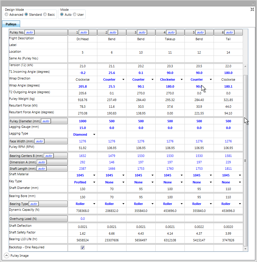
Everything in blue is editable. Everything that is red indicates an out-of-spec condition.
The columns and rows headings including the ![]() button can be reset to automatic recalculation by clicking the button.
button can be reset to automatic recalculation by clicking the button.
This data is the same as discussed in Basic Input.
•In "User" mode the Pulley Weight is estimated. In "User" mode, this value can be overridden with user input.
•Minimum shaft safety factor, maximum shaft deflection for fabric belt, maximum shaft deflection for steel cord belt and desired bearing L10 life are all factors that can be set in the customized defaults screen.
Shaft safety factor and deflection calculations are in accordance with the CEMA manual.
•The minimum Shaft Diameter input in the user mode is 75% of the nominal shaft size.
•If required, the backstop is automatically located on the head pulley and the required torque is displayed. However, this location can be changed (see Select Backstop).
As the user scrolls across the columns from one pulley to the next, a sketch is provided for each pulley. The sketch is interactive so the user can determine the effects of items such as T1 Incoming Angle and Wrap Direction. Sketches of each pulley are included in the printout.
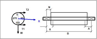
The pulley sketch can be dragged to a position either below the specification table or to the right depending on the user's display preference.
See Also: Pulley Basic Input, Pulley Advanced Design, Pulley Spreadsheet Shortcuts