|
<< Click to Display Table of Contents >> Pulley Advanced Design |
  
|
|
<< Click to Display Table of Contents >> Pulley Advanced Design |
|
Available in Pro and Above
Updated in v20.1
The "Advanced Design" approach uses specific hubs, shafts and bearings contained in a database to assist in the selection of pulley components and design. Shaft deflection, shaft safety factor, hub safety factor, turndown safety factor and bearing life are estimated.
The Pulley tab opens a page of pulley loads, description, components and dimensions. While the loading is primarily input from the conveyor design, default dimensional values and selected components can be overridden. Lagging and basic dimensions are overridden directly while shafts, hubs, and bearings are selected from a database which includes the component design data as well as categories or manufacturers desired for the particular conveyor being designed. Editable data files are provided for several components commonly used for pulley construction.
The subcomponents are selected by methods described and inferred by CEMA’s Belt Conveyors for Bulk Materials Chapter 8 and the manufactures catalogs. Pulley calculations do not include specification for the pulley construction. Rotating shaft designs are supported.
Only User mode is available for the Advanced Design approach.
▪When the "User" mode is chosen, the user may input T1 Incoming Angle, Wrap Direction, Wrap Angle,
The user may also select Pulley Diameter, Lagging Gauge and Type, Face Width, Bearing Centers, Shaft Length, Shaft Material, Key Type, Bearing Seal Type, and Overhung Load. The software selects all other parameters.
The user can also edit Pulley Weight, Hub Series and ID, Shaft Diameter, and Bearing Series and ID.
When reopening a conveyor file (*.an2) that was saved by an earlier version of Belt Analyst that did not have this design option, the Pulley tab page will open using the Standard Design approach.
Right clicking on Flight Description cell will show error messages.
Right clicking on Pulley Weight, Pulley Diameter, Face Width, Bearing Centers or Shaft Length will give the user the option of resetting the selected value to default values for all pulleys.
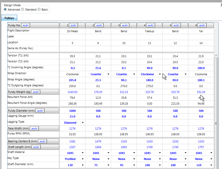
Everything in blue is editable. Everything that is red indicates an out-of-spec condition.
The columns and rows headings including the ![]() button can be reset to automatic recalculation by clicking the button.
button can be reset to automatic recalculation by clicking the button.
If the pulley Description is yellow (warning) or red (problem), right clicking on the cell will show a message explaining the issue.
On the printed report, these error messages will print over the pulley sketch.
This data is the same as discussed in Basic Input.
•In "User" mode the Pulley Weight is estimated. In "User" mode, this value can be overridden with user input.
The pulley hub is defined as the internal, rotating, clamping component that connects the pulley to the shaft. The Hub design establishes the inset used in combination with the bearing center and face width for calculating the pulley bending moment and required shaft size. In addition, the Hub has an allowable rotating moment and torque that sets the Hub SF (safety factor) output. All of the shaft moment is assumed to be supported by the Hub. (Rigid pulley with no disc or rim flexibility).
An iterative selection is used in ”Auto” mode to find an acceptable shaft and hub combination that satisfies the various design criteria. The hub description is generic for a hub of this size.
•In "User" mode, the Hub Series can be from the drop-down list of hub series contained in the database.
The Hub Series can be returned to the default specified in the Customized Defaults by selecting "Default" from the pull-down list. When this is done, the program will select a hub consistent with the shaft and pulley. If there is a problem with this selection, it will be discussed in the error messages.
•In "User" mode, the Hub ID can be from the drop-down list of components from the selected Hub Series compatible with the shaft selection.
The program will select a hub consistent with the shaft if "Auto" is selected in the pull-down list. If there is a problem with this selection, it will be discussed in the error messages.
The range of hubs available for selection and their specification can be set using the Edit Pulley Database menu item.
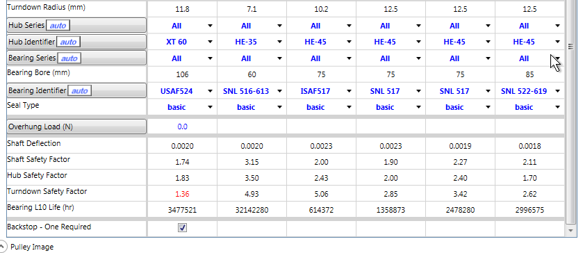
The resulting shaft stress, deflection and hub capacity as a safety factor on the design criteria are displayed lower in table. The torque limit is not used if the hub is keyed.
In advanced mode, there are two inputs for pulley shaft diameter. The Shaft Diameter input is the same as the Hub Bore (ID) and must be compatible with the selected hub/locking assembly. The Shaft Diameter Between Hubs input is the pulley shaft diameter in the middle of the pulley shaft, between the pulley locking assemblies, and is also the value used to calculate shaft deflection. The shaft diameter sets the bearing centers in combination with the face width unless manually overridden previously. The shaft material and key type affect the shaft stress calculations for the Shaft SF. Shaft length impacts the weight and sketch only.
•The shaft diameter inputs can be selected in User mode from a pull-down list of appropriate shaft sized in the database.
Both English and metric shaft sizes are displayed in the units selected for BA.
•Turndowns can be utilized to allow bearing bores less than the hub bore.
The use of turndowns is controlled by the Allow Turndowns, Maximum Turndown Ratio and Limit Turndowns to 90º settings in pulley section of the Customized Defaults menu item.
An acceptable bearing bore and bearing capacity combination are set by the turndown stress and bearing life for the particular bearing being considered. Larger turndowns are desirable for reduced stress but there must be space available. In both ”Auto” and ”User” modes, Belt Analyst only allows turndowns that fit the space dictated by bearing center, face width, bearing width, added seal width if applicable, bearing clearance and turndown radius arc. The maximum allowable radius for stress and space is displayed. Smaller radii may be unsafe while larger may not fit. Independent verification is suggested if alternate radii are to be considered.
•In "User" mode, the Bearing Series can be from the drop-down list of bearing series contained in the database.
The Bearing Series can be returned to the default specified in the Customized Defaults by selecting "Default" from the pull-down list. When this is done, the program will select a bearing consistent with the shaft and pulley. If there is a problem with this selection, it will be discussed in the error messages.
•In "User" mode, the Bearing ID can be selected directly from the drop-down list of acceptable options. Specifications for the selected bearing can be viewed by right clicking on the Bearing ID cell.
The program will select a bearing consistent with the shaft if "Auto" is selected in the pull-down list. If there is a problem with this selection, it will be discussed in the error messages.
The range of bearings available for selection and their specification can be set using the Edit Pulley Database menu item.
•The Bearing Diameter and Bearing Type are determined the Bearing ID selection.
•The provision for an alternate or auxiliary Bearing Seal Type is provided. Its use must be selected directly. Space issues discussed under turndowns are evaluated and may limit the use of alternate seals.
•Minimum shaft safety factor, maximum shaft deflection for fabric belt, maximum shaft deflection for steel cord belt and desired bearing L10 life are all factors that can be set in the customized defaults screen.
Shaft safety factor and deflection calculations are in accordance with the CEMA’s Belt Conveyors for Bulk Materials 6th Ed manual.
As the user scrolls across the columns from one pulley to the next, a sketch is provided for each pulley. The sketch is continually updated so the user can determine the effects of items such as T1 Incoming Angle and Wrap Direction. Sketches of each pulley are included in the printout.
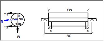
The pulley sketch can be dragged to a position either below the specification table or to the right depending on the user's display preference.
See also: Pulley Basic Input, Pulley Standard Design, Pulley Spreadsheet Shortcuts