|
<< Click to Display Table of Contents >> Trajectory |
  
|
|
<< Click to Display Table of Contents >> Trajectory |
  
|
Available in All versions
Available in All Program Levels
Updated in v14.0

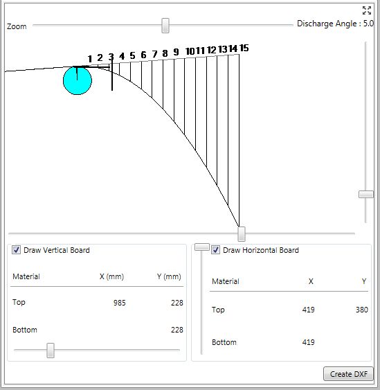
The Trajectory page is accessed by single clicking on the Trajectory tab on the Home menu item. It can be expanded by using the Resize "X" screen button in the upper right corner of the window.

The trajectory picture can include a horizontal and vertical board for determining the coordinates of the material flow at a given point.
•The X and Y coordinates are given at the points where the horizontal and vertical boards intersect the top and bottom of the material flow. The center of the pulley is the zero, zero (0,0) coordinate position.
•The vertical scroll bar is used to move the Horizontal Board.
•The horizontal scroll bar is used to move the Vertical Board.
•The Belt discharge angle is equal to the angle of the carry flight closest to the head in the Profile Tab.
•The Make DXF button will produce a DXF file of the trajectory that can be imported into a drawing program such as AutoCAD. The drawing is done in inches if English units are selected or millimeters if metric units are selected. The pulley diameter comes from the head pulley diameter in the pulley section and the material bed depth comes from the material section.
•A check in the Vertical Board from Pulley Center or Horizontal Board from Pulley Center includes the respective board in the onscreen drawing and DXF file. Likewise, removing the check eliminates the respective board.
The trajectory picture can be zoomed and paned.
•The upper horizontal scroll bar enlarges or contracts the onscreen drawing.
•The lower horizontal scroll bar changes the horizontal position of the onscreen drawing.
•The right vertical scroll bar changes the vertical position of the onscreen drawing.
•The onscreen image determines the image in the printout but does not affect the scaled DXF drawing.