|
<< Click to Display Table of Contents >> 2D Graphic Input |
  
|
|
<< Click to Display Table of Contents >> 2D Graphic Input |
|
Available in v16 and higher
Available in Standard
Updated in v20.1
When in the Advanced User mode for the conveyor profile, the profile view includes both the table of flight data and a 2-dimensional drawing of the profile. This drawing can be manipulated to edit and add flight and pulley data.
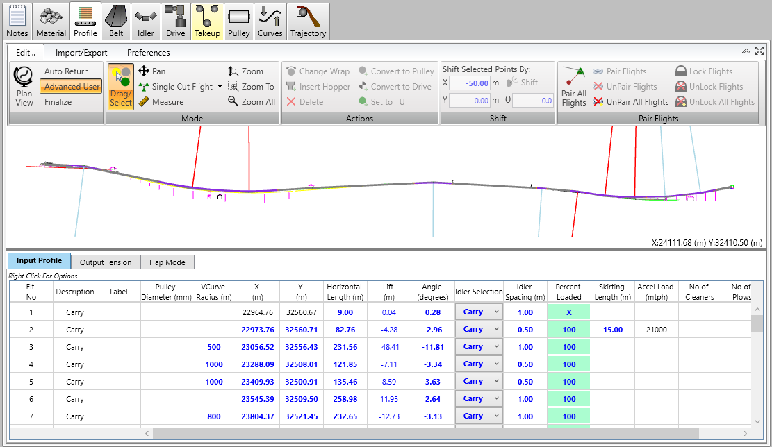
Some of the drawing conventions used are:
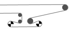
•Drive pulleys on the head or tail pulley are shown as a orange checkered circle,
•Other drive pulleys are shown as a black checkered circle,
•The takeup pulley is green,
•Other pulleys are gray,
•When the pulley is selected, it is shown as yellow,
•When a belt flight is selected, it is shown as yellow,
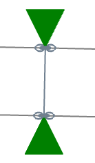
•When flight points are paired, a chain notation is shown at points.
•The loading area is shown with a chute outline,
Material loading is not shown.
The drawing can be navigated using the Edit > Mode menu commands and mouse.
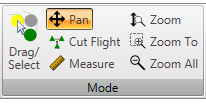
•Pan allows the user to move the displayed portion of the drawing using the mouse,
•The mouse scrolling wheel allows zooming in or out from the current view,
•The Zoom buttons allow zooming to specified parts of the drawing.
The X and Y coordinates of the cursor are shown in the lower right corner of the drawing.
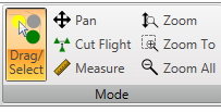
•Drag/Select allows the user to select a pulley or belt flight point by left clicking on it. This will also highlight and select the pulley in the data table. The pulley can be relocated by left clicking and dragging the pulley.
While using the drawing to modify the pulley location, the data table below can be used to change the size of the pulley.
The user can save current and retrieve specified views. The pop-up menu is called by right clicking on the drawing window.
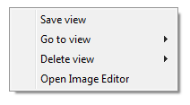
•Save stores the current view. It is defined by the number and the X-Y coordinates of the center.
•Go To navigates to a previously saved view.
•Open Image Editor goes allows stored views to be arranged and saved for including in a document.
The Preferences tab allows the user to select profile drawing display options.
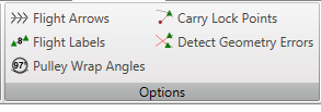
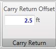
•Carry Lock Points ensures that the carry Return Offset dimension is utilized.
•Detect Geometry Errors turns flight segments red when the program detects a possible error, such as overlapping belt.
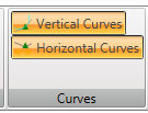
Vertical and horizontal curves can be shown on the drawing by clicking on the buttons in the Preferences > Curve menu.
Using the Preferences > Carry Return menu, the distance between the carry side belt and the return side can be set.
Using the Preference > Shift menu, the coordinates of the conveyor starting point can be entered. The starting point for the profile description is always the tail pulley.
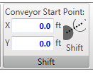
The starting point coordinates are sometimes changed to get the conveyor stations on this BA drawing to agree with another drawing.
See Also: Editing Profile, Paired Flights, Finalize Profile