|
<< Click to Display Table of Contents >> Selection of Pulley Diameters with the DIN Method |
  
|
|
<< Click to Display Table of Contents >> Selection of Pulley Diameters with the DIN Method |
|
Available in v1?.0 and higher
Available in All Program Levels
Updated in v16.0
The DIN 22101 standard specifies that the selection of pulley diameters should be done according to the following:
The minimum pulley diameters of a belt conveyor installation will be determined by the design and layout, stresses and splicing method of the belt. A distinction is made between the following groups of pulleys when determining the minimum pulley diameters:
•Group A: drive pulleys and all other pulleys in the zone of high belt tension
•Group B: return pulleys in the zone of low belt tensions
•Group C: deflection (snub) pulleys (wrap angles ≤ 30 degrees)
If DIN standards and other normative regulations do not provide further relevant details, the minimum diameters of Group A pulleys, for the four different groups of pulley load factors provided in [Table Below] can be determined as follows:
![]()
dTr – is the estimated minimum pulley diameter for Group A pulleys
dGk – is the thickness of the carcass of the selected belt
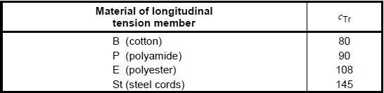
cTr – is a parameter dependent on the carcass material as shown in the table below.
Each diameter determined for Group A pulleys in accordance with the above description shall be rounded up to the next standard value indicated in the table below. The minimum diameters of Group B and C pulleys shall be chosen in relation to the pulley load factor in the table below that is relevant for Group A pulleys on the conveyor being evaluated.
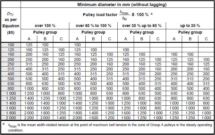
To further define the equation for the pulley load factor at the top of the above table, the following definitions are given:
kmax – is the highest steady state belt tension located next to a group A pulley.
KN – is the breaking strength of the selected belt
Pulley locations for the conveyor being evaluated within Belt Analyst™ are determined from the where the user places the pulleys on the flights tab. It is up to the user to define accurate pulley wrap angles by either using the pulley wizard on the flights tab, or by manually inputting the wrap angles on the pulley tab. Given the pulley locations, Belt Analyst™ can automatically determine the belt tension and associated resultant load for every pulley defined on the flights tab.
Belt Analyst performs a basic grouping of the pulleys into the DIN specified pulley groups based upon the following logic:
•All drive pulleys are automatically classified as DIN group A pulleys.
•All pulleys with a wrap angle of 30 degrees or less are classified as DIN group C pulleys
•All other pulleys are classified as DIN group B pulleys.
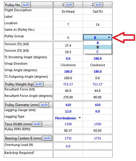
Belt Analyst™ only performs an initial guess for the DIN group classification. It is the user’s responsibility to classify the pulleys into their proper DIN group based upon the definitions in the DIN 22101 standard. This can be done by adjusting the pulley group input for each pulley on the pulley tab (as shown below).
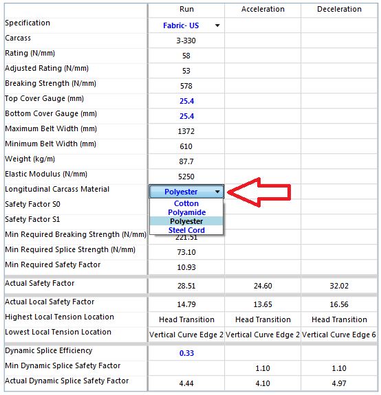
To ensure proper definition of the minimum required pulley diameter for each pulley, the user must also define more specifically the carcass material on the belting tab as required by the DIN method (as shown below).
Belt Analyst™ uses this information, along with the carcass thickness (grabbed from the belting data for the selected belt), and finds the Group A pulley that has the highest belt tension around itself. The pulley load factor calculation is done for that pulley to determine which columns to use on the “minimum pulley diameter table” and the estimated pulley diameter calculation is used (rounded up) to determine which row on the “minimum pulley diameter table” should be used. The result is a defined minimum pulley diameter to use for each group of pulleys. The input pulley diameter must be larger than these determined diameter values or the text will show red. The user can delete whatever pulley diameter that has been input to have the program output the result of this minimum pulley diameter calculation.
To reiterate, the minimum pulley diameter for each DIN group of pulleys is determined from the pulley load factor calculated from the group A pulley that sees the highest steady state tension on the subject conveyor, and the calculation for the estimated group A pulley diameter as described in the section above.