|
<< Click to Display Table of Contents >> Selection of Belting with the DIN Method |
  
|
|
<< Click to Display Table of Contents >> Selection of Belting with the DIN Method |
|
The DIN 22101 standard states that, when selecting and evaluating the required breaking strength of a belt to be applied to a conveyor, the ultimate safety factor between breaking strength and steady state running tensions should be a calculated value based upon the operating conditions of the belt and splice quality.
The DIN 22101 standard states the following regarding the selection of a conveyor belt for a conveyor:
The tension members and cover layers of a conveyor belt shall be selected according to the operating conditions. Their specification will be governed to a considerable extent by the characteristics of the bulk material conveyed (physical and chemical characteristics, gain structure) and by the application conditions of the belt (environmental influences, scheduled service life, mechanical stresses, and feed point requirements).
The dynamic strength of the conveyor belt verified for vulcanized splices on a test stand according to DIN 22110-3shall form the basis for the selection of conveyor belts and splices. The design and layout shall be based on the reference dynamic splice efficiency kt as defined in the above-mentioned test procedure (DIN 22110-3)
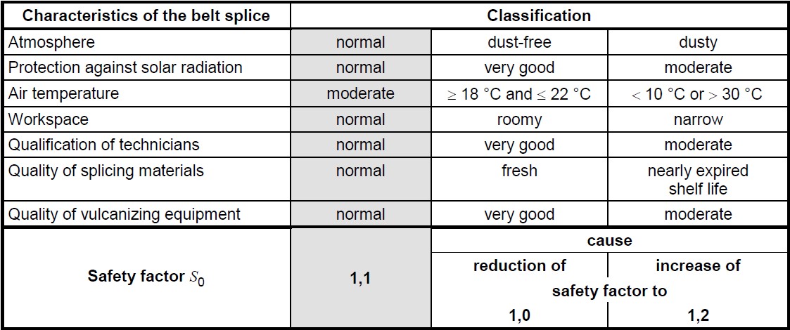
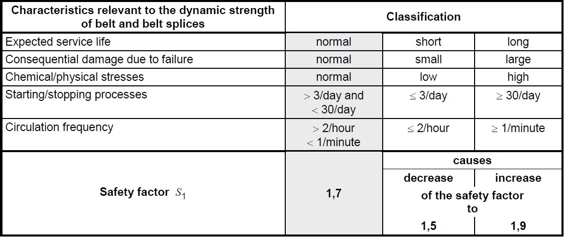
The values of the dynamic splice efficiency are established for splices made and tested under ideal conditions. Deviations from these conditions, either related to the situation or due to the operating conditions, shall be taken into account by applying a safety factor S0,which shall be established in accordance with [First table shown below]. Chemical and physical stresses, influences of natural aging, and the frequency of high tensions and bending stresses are represented by factor S1 from [Second table shown below].
At this stage, the design and layout shall be based on the highest belt tensions calculated for a belt cross section in the steady state condition.
Based upon the user selected factors from the tables above, a “minimum dynamic splice efficiency kt,min” of the belt and belt splice can be calculated with the following equation:
![]()
where,
kt,min – is the minimum required dynamic splice strength (DIN 22110-3) of a selected belt
kK,max – is the maximum belt stress that occurs during steady state operation across the width of the belt (accounting for local stress variations such as vertical curves and transition zones)
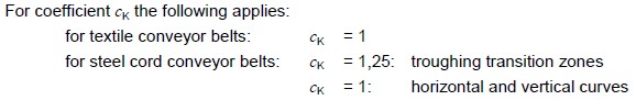
cK – is a coefficient to adjust and account for belt carcass type and where the stress kK,max occurs according to the following:
In turn, the minimum required nominal breaking strength of the belt kN,min can be calculated from the following equation:
![]()
kN,min– is the minimum required nominal breaking strength of a selected belt
kt,min– is the minimum required dynamic splice strength of a selected belt
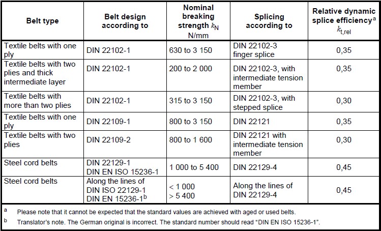
kt,rel– is the relative dynamic splice efficiency of the selected belt. Values for kt,rel can be obtained from the DIN 22110-3 test. Typical values for design purposes can be obtained from the following table.
With a required breaking strength for the belting calculated, we can rework the numbers to calculate out a minimum required safety factor (breaking strength to steady state operating tension) for the belt:
![]()
Smin– is the minimum required safety factor of belt breaking strength to steady state operating tension
k – is the maximum steady state belt stress (nominal stress across the width of the belt)calculated for the conveyor.
Because none of the equations above take into account the possibility of extremely high dynamic belt stress, a check needs to be made to ensure that the dynamic (starting and stopping, temporary loading conditions) belt stress does not come too close to the dynamic splice strength, as described by the following equation:
![]()
where,
kt,min– is the minimum required dynamic splice strength for the belt.
cK– Is the coefficient described above in the kt,min calculation.
KK,a,max– is the maximum belt stress that occurs during dynamic conditions. This value needs to account for local belt stresses such as curves and transition zones.
The selected belt for a conveyor needs to meet all the above requirements.
Each belt evaluated in Belt Analyst™ for a specific conveyor is evaluated to ensure that the steady state belt tensions meet the minimum required safety factor as described in the section above. Furthermore, each belt has its estimated dynamic tensions evaluated to ensure that the dynamic tensions do not come too close to the dynamic splice strength (as shown in the final equation in the above section).
To perform this evaluation the user must input the following DIN specific belting information into Belt Analyst’s belting tab:
•Safety factor S0 – as per the table shown in the section above
•Safety factor S1 – as per the table shown in the section above
•Dynamic Splice Efficiency – as per DIN 22110-3 testing or the table shown in the section above
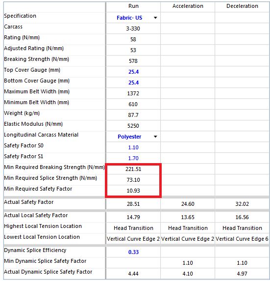
Belt Analyst™ will then take this input and automatically grab the calculated belt stresses and belting component information from the belting component database to perform the necessary calculation. As an output onto the belting tab, Belt Analyst™ outputs the calculated minimum required breaking strength of the belt, minimum required splice strength, and minimum required safety factor. The actual safety factor during running (steady state) of the selected belt must be larger than the minimum required safety factor for the belt to be considered acceptable. These outputs are shown in the image below:
A note for the user when selecting a belt – when the belting tab is put into auto mode, Belt Analyst™ is attempting to select a belt from whichever belting database the user has selected that minimizes the breaking strength of the belt while still meeting the DIN safety factor requirement. As shown in the section above, the required DIN safety factor calculation is dependent upon the local stresses predicted within the belt. The user should know that this safety factor will change (sometimes drastically) when local tension areas are addressed within the design. Properly sizing vertical curves, transition, turnovers, and other local tension factors has a great effect upon what belt should be selected.
Because of this fact, the auto-mode selection of vertical curve radii may not work properly within the DIN mode. This is because the Belt Analyst™ auto mode for all tabs is set to minimize component sizes (or curve sizes) while maintaining acceptable design criteria. If the highest local tension exists within a curve on a conveyor, and Belt Analyst™ is attempting to minimize the curve radii (thus increasing local tensions), the selection of the belt may be adversely affected due to an increased safety factor requirement. The user should take note of situations like this and choose to manually adjust curve and belting selection to ensure an optimal balance is achieved. This is also true for the selection of other local tension zones such as transition zones.