|
<< Click to Display Table of Contents >> Material Calculations and Considerations |
  
|
|
<< Click to Display Table of Contents >> Material Calculations and Considerations |
|
The calculation of the maximum volume and mass flow of a conveyor within DIN 22101 differs from the CEMA calculation method. Where CEMA uses a rounded estimate for the shape of the material cross-section on the conveyor (left image below) DIN uses a shape with a ridge at the center (right image below). This ultimately means that the maximum available volume and mass flow differs between the two methods. The DIN 22101 method will be described here and how it is implemented into the Belt Analyst™.
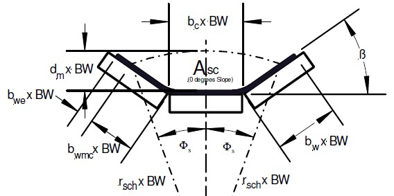
As per the volume and mass flow section of the DIN 22101standard (refer to the diagram above for understanding of some variable definitions):
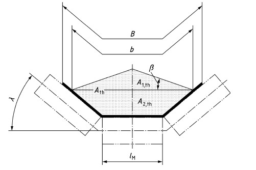
To calculate the maximum volume and mass flow [of a conveyor] a simple equivalent geometrical cross section needs to be found. This theoretical cross section Ath , is calculated from the shape of the conveyor belt on the carrying idlers and from the shape of the slope formed by the material conveyed.
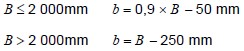
The theoretical cross section of the fill is dependent on the length and arrangement of the carrying idlers, the usable belt width b and the equivalent slope angle β describing ta cross section of the same area as the actual one. In this case, the usable belt width b shall be calculated as a function of the belt width B as follows:
The theoretical cross section of fill Ath that is equivalent to the real cross section of fill can be established using angle β as the sum of partial cross sections A1,th and A2,th.(see cross section diagram)
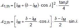
lM – Length of the center roll of the idler set (0 for 1 or 2 roll sets)
b – Usable belt width, as described above.
λ – Idler set troughing angle
β – Equivalent angle of slope
The selection of an equivalent slope angle depends on the material to be conveyed as well as the length of the conveying distance. In case of lacking experience in selecting an adequate slope angle, the following standard value scan be applied:
The value will be β=20 deg for materials with normal flow properties. Values below β=20 deg down to β=0 deg will be characteristic for nearly liquid materials. Equivalent slope angles of more than 20 degrees can be applied only in case of materials with high internal friction.
The above information can be used to calculate a maximum allowable cross sectional area for the material on the conveyor. A filling ratio φ is then calculated to adjust the maximum available space to account for a reduction in available space when the material is traveling in non-flat sections of the conveyor and to account for the fact that the angle of slope may reduce itself (to βDyn)as the material travels along the conveyor. This filling ratio φ is calculated according to the following equation.
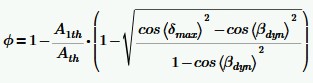 where,
βdyn is the dynamic angle of slope
δmax is the maximum angle of inclination along the conveyor
The filling ratio is used to adjust the maximum available area according to the following equation:
![]()
A maximum available volume and mass flow can be calculated from the final maximum available area (AA) and a comparison with a desired volume and mass flow can be made to calculate a percentage fill for a conveyor calculation.
Application of DIN Volume and Mass Flow Calculations within Belt Analyst™
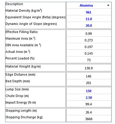
A drawing of the cross-sectional area of the material and idlers is continually updated within Belt Analyst to give the user insight into the available space on the conveyor. A percentage loading is also shown at the bottom of the program.
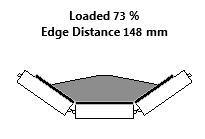
All the geometry necessary to perform the calculation and draw the cross-section is automatically grabbed from the user input data for the idlers, belting, design capacity, and material. This includes belt width, capacity, conveyor speed, idler troughing angle, idler roll length, and maximum angle along the conveyor profile. The user can edit any of these bits of data within the associated component tab to adjust the results of the calculation.
Specific user inputs for equivalent slope angle (β) and dynamic angle of slope (βdyn) are required to be input on the material tab to properly perform the material calculation.
To calculate the percentage loading the DIN available area is compared to the actual area required to convey the input conveyor capacity. The table below is from a screen shot of the material tab when Belt Analyst has been put into DIN calculation mode.