|
<< Click to Display Table of Contents >> Drag Calculation or Resistance to Motion |
  
|
|
<< Click to Display Table of Contents >> Drag Calculation or Resistance to Motion |
|
Perhaps the most important aspect of any conveyor design is how the resistance along the conveyor during steady state operation is calculated. The DIN 22101 standard breaks drag or resistance to motion into 4 categories. The sum of the 4 types of resistance to motion FW is equal to the total pulley peripheral force FTr to be transmitted to the belt:
![]() Where,
Where,
Primary resistance is FH
Secondary resistance is FN
Gradient resistance is FSt
Special resistance is FS
Each resistance category is described below along with how these resistances are input or calculated within Belt Analyst™
The primary resistance is the measure of the friction associated primarily with the rolling resistance of the idlers, indentation rolling resistance of the belt, and the flexing resistance of the belt (belt deforming due to sag). The primary resistances of each section or flight of a conveyor are determined separately for the carry and return (upper and lower strands) portions of the conveyor. The following equations describe how the Primary Resistance FH is calculated:
![]() where,
where,
FH_O is the primary resistances from the carry side
FH_U is the primary resistances from the return side.
The primary resistance of any section (flight) or conveyor, carry or return can be described in the following equation:
![]() where,
where,
l - is the length of the section or flight of conveyor being calculated
f - is the hypothetical friction coefficient for the subject section of conveyor
g - is the acceleration due to gravity
mR - is the mass per length of conveyor associated with rotating idler parts
mG - is the mass per length of conveyor associated with the conveyor belt
mL - is the mass per length of conveyor associated with the conveyed material
d - is the angle of inclination for the evaluated section of conveyor
The estimate for primary resistance is done for each section or flight of the conveyor you are calculating as follows:
•Each flight that has been input into Belt Analyst’s flight tab will have its primary resistance evaluated according to the above equation.
•The length and angle of inclination will automatically be grabbed for each flight from the flights tab.
•The mass of the idlers, belting, and material will be automatically grabbed from the user inputs for each component’s mass on each component’s input tab within Belt Analyst™. Idler spacing and percent loading for each flight will be taken into account as the user has input on the flights tab.
•The hypothetical friction coefficient is a user input that the user must input into the Belt Analyst program according to his/her own expertise.
•Belt Analyst has the ability to input a different hypothetical friction coefficient for the carry side and return side of the conveyor. These friction factors can be input one of two ways:
•A form will pop up asking for the friction coefficients when you select the DIN calculation method for the first time from the calculation method menu item at the top of the program.
•A form will pop us asking for the friction coefficients when you click on the white friction coefficients display area on the bottom right side of the program.
![]()
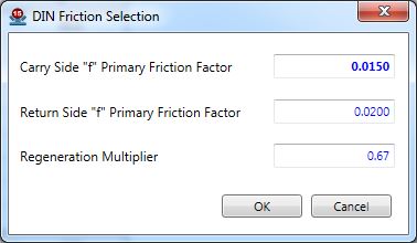
•The input form for the friction coefficients looks like the following image. Please note that the friction coefficient input for the carry side will be used for every flight located on the carry side of the conveyor and the friction coefficient input for the return side will be used for every flight located on the return side of the conveyor.
•There is also an input for “Regeneration Multiplier”. This multiplier is applied to the primary resistances when it is estimated that the forces of gravity on the material will overcome all the resistance on the conveyor and the required power to operate the conveyor becomes negative. Having a multiplier below 1 introduces some conservatism into the calculations of a regenerative conveyor as the highest power demand requirement may be associated with the lowest drag estimate. Again, this multiplier is only applied if the power requirement on the conveyor becomes negative in the active calculation case.
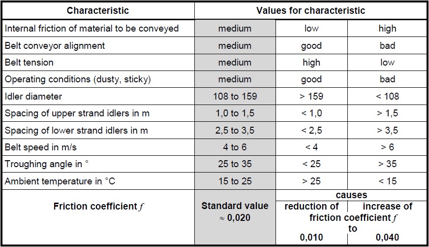
For the selection of the friction coefficients, the DIN standard provides the following insight:
If there are no values which have been obtained by measurement or on the basis of experience or if only an approximate dimensioning is intended, standard values for the hypothetical friction coefficient f can be selected from [Table shown below] for estimating the total primary resistance of the upper and lower strands on the basis of operating conditions and design features. These values are based on numerous combined upper and lower strand measurements and for the following limiting conditions:
•3 roller fixed idler sets in the upper strand
•Carrying idlers with anti-friction bearings and labyrinth seals
•Values of relative sag less than 1%
•Filling ratio φ within a range of 0.7 to 1.1
For further clarification on the selection of friction coefficients, the DIN standard also says:
For a more precise determination of the friction coefficient f aiming for a safe conveyor design combined with a minimum investment and lower operational costs, the running resistance of the idlers and the indentation rolling resistance can be measured for given parameters and the other resistances can be estimated [see DIN 22101 standard for more information].
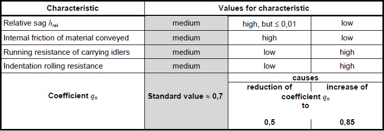
With a normal magnitude of flexing resistance the running resistance of the idlers and rolling indentation resistance of the loaded strand (usually the upper strand) with a filling ratio φ within the range of 0.7< φ<1.1, generate between 50% and 85% (on average 70%) of the primary resistance FH,O. They amount to approximately 90% of the primary resistance for the unloaded strand (usually the lower strand) FH,U. Consider the following relationships apply
![]()
![]()
With 0.5 < qo <0.85, on average qo=0.7 and qu=0.9
FR - is the running resistance of the idler sets (given as a force)
FE - is the running resistance due to belt rubber indentation (given as a force)
Secondary resistances include frictional resistances and inertia resistances that exist only on certain portions of the conveyor. These resistances are calculated from several individual resistances and include frictional losses due to skirting drag on the belt, material drag on skirting, inertial acceleration of material, cleaners and plows as described in the following equation:
![]()
FN - is the total secondary resistance on the conveyor
FAuf - is the estimated resistance due to accelerating the material at the feeding point of the conveyor
FSchb - is the resistance due to skirtboard drag on the belting as well as material resistance against the skirtboard.
FGr - is the estimated resistance due to belt cleaners and plows.
Please refer to the DIN 22101 standard for specifics on how to calculate each secondary resistance. The DIN 22101 standard does provide a general guideline for the estimation of the total secondary resistance on a typical conveyor:
If the portion of the secondary resistances in the total resistance is small, e.g. with conveyor lengths L >80m and the conveyor has just one feeding point, an approximate calculation of secondary resistances FN from the primary resistance FH applying coefficient C according to the following equation and table is permissible:
![]()
The coefficient C can be selected from the following table (L is the center to center length of the conveyor):

Secondary resistances are calculated within Belt Analyst™ at each location that the resistance exists on the conveyor. For example, if a cleaner has been placed on a flight just following the head pulley, Belt Analyst will add the resistance of the cleaner to the resistance of that flight (just following the head pulley) that the cleaner exists on.
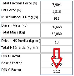
There is no input for a DIN C coefficient within Belt Analyst™. Each secondary resistance is calculated and added to its associated flight. A DIN C coefficient is then calculated as an output for user reference according to the equation listed in the above Secondary Resistances section of this document.
Material Acceleration Resistance (FAuf)– This resistance is automatically added to the first flight along the carry side of the conveyor that has load AND skirting. This can be seen in the following screen shot; on the flight input with Belt Analyst, a material acceleration load (in this case 2000 mtph worth due to the user input capacity for the conveyor) has been added to the first flight that has a percentage load above zero and also has a skirting length input.
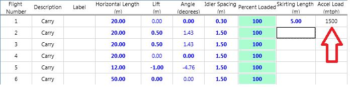
It should be noted that this calculation is directly linked to the user input capacity of the conveyor and the percentage loading input for the flight. The output of this calculation is added to the “Misc Drag” output for the flight. This output is located on the “Output Tension, Drag, Mass, etc…” tab within the flights tab.
Skirtboard Resistance (FSchb) – This resistance is automatically added to any flight that has a user input skirtboard length on the flights tab. The resistance of the skirtboard pressing against the belt is estimated according to an assumed skirtboard resistance. This assumed resistance is a default that can be changed in the customizable defaults of the Belt Analyst program (listed under “Accessories”). The resistance of the material against the skirtboard is also calculated. The output of the skirtboard resistance calculation is added to the “Misc Drag” output for the flight. This output located on the “Output Tension, Drag, Mass, etc…” tab within the flights tab.
Cleaner and Plow Resistance (FGr) – This resistance is automatically added to any flight that has a user input number for a cleaner or plow on the flights tab. The resistance of cleaners and plows is estimated according to an assumed cleaner/plow resistance. This assumed resistance is a default that can be changed in the customizable defaults of the Belt Analyst program (listed under “Accessories”). The output of the cleaner/plow resistance calculation is added to the “Misc Drag” output for the flight. This output is located on the “Output Tension, Drag, Mass, …” tab within the flights tab.
Please note that Belt Analyst™ estimates the resistance of pulley bearings and the resistance of bending the belt around a pulley. These resistances are also added to the secondary resistances and used within the calculation of the DIN C coefficient. DIN 22101 recognizes these resistances as secondary resistances but states these resistances “… can be neglected in almost all cases.” These resistances are not neglected with Belt Analyst™ calculations.
The output for the DIN C coefficient can be seen on the bottom right portion of the screen and also within the “Summary Data” tab located on the Drives tab.
![]()
Gradient resistance is simply the resistance to conveyor movement associated with gravity and any conveyor lift (or change in height) along a section of conveyor. This gradient resistance can be calculated for any flight with the following equation:
![]() where,
where,
FSt - is the gradient resistance of the flight
h - is the conveyor lift or change in height of the flight
g - is acceleration due to gravity
mG - is the mass of the conveyor belt on the flight
mL - is the mass of the conveyed material on the flight
The gradient resistance is calculated for every flight input into Belt Analyst on the flights tab. Conveyor belt mass and material mass are automatically grabbed from the user inputs for material, capacity, percentage loading for each flight, and belting for the calculation. Please note that the input percentage loading for each flight on the flights tab is taken into account for the calculation of the gradient resistance.
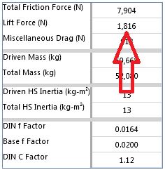
The total gradient resistance for the whole conveyor is output as “Lift Force” within Belt Analyst. This output is located on the “Summary Data” tab located on the Drives tab.
As per DIN, special resistances are resistances that do not occur with all belt conveyors. These special resistances can be summarized in the following equation:
![]() where,
where,
FS - is the special resistance for a conveyor flight
FRst - is the resistance due to the camber of an idler set (forward tilting)
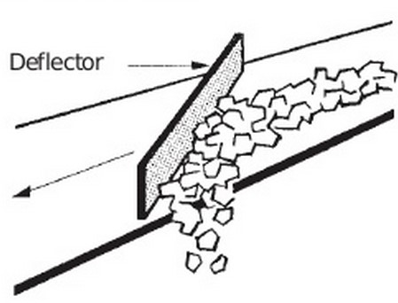
FSch - is the resistance due to material drag against skirtboards beyond the loading zone
FGa - is the resistance due to the use of a scraper as a method of discharging material laterally at some point along the conveyor.
Idler Camber Resistance (FRst) – If idlers are tilted in the direction of belt travel on the conveyor being analyzed, the best way to account for this within Belt Analyst™ when using the DIN 22101 method is to select a higher primary resistance f factor than you would otherwise. Tilting of idler sets along a conveyor affects every flight that has the tilted idler sets (in practice, typically all flights would have tilted idler sets).
Material Resistance Due to Skirting Outside of Loading Zone (FSch) – This resistance is automatically calculated within Belt Analyst™ by adding a length of skirting on any specific flight on the flights tab. Belt Analyst™ will automatically recognize if a loading zone already exists that has accelerated the conveyor load, and treat any skirting outside of that loading zone as simply skirting without the need for material acceleration. Skirting drag against the belt and material will still be calculated. This number will be added to the miscellaneous drag output and the calculation of the DIN C coefficient.
Resistance Due to a Lateral Scraper Discharge (FGa) – This resistance is not calculated automatically within Belt Analyst™. To account for a discharge of this type, the user must manually calculate the resistance and then input the drag into the “Extra Drag” column of the flight where the discharge exists on the flights tab. Refer to DIN 22101 on how to calculate this drag.