|
<< Click to Display Table of Contents >> Fluid Coupling |
  
|
|
<< Click to Display Table of Contents >> Fluid Coupling |
  
|
A fluid coupling is employed between the motor and reducer to "soften" the motor start. The driven impeller (connected to the motor) drives the runner (connected to the driven conveyor) by the action of the fluid contained in the coupling's casing. When the motor first starts, there is minimal load since the fluid has not flowed between the impeller and runner. As the motor accelerates, the oil begins to pump and torque gradually increases. When the torque level reaches the necessary breakaway value, the runner will start to rotate and accelerate the conveyor. The motor is typically running at full load speed.
Different fluid fill levels will provide different torque values. More fluid in the coupling provides higher starting torque and more available torque for acceleration. In some cases it is desirable to limit the maximum starting torque when there is a large difference between loaded and unloaded conditions; fluid couplings with a delay chamber allow additional fluid to be added to the circuit.
Thermal considerations should be addressed when fluid couplings are utilized.
The control routines are defined by inputting the torque transmittal curves.
1.Select "Fluid Coupling" on the motor control pull-down list.

The fluid coupling control option is only available for starting cases.
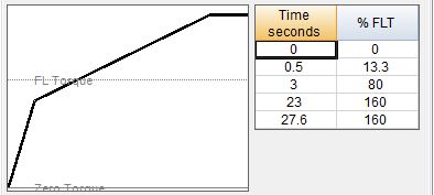
2.The initial and final torque levels, and the time between these two values must be input. For a fixed fill level, the two levels should be the same.

The torque data is entered in these boxes and displayed on the data table and the control curve chart; the data table cannot be directly edited. A more complex torque curve can be constructed using the Torque control if desired.

3.Drive can be set to start after start of simulation. This option can be used to stagger the start times of multiple drives.
![]()
4.Control sequence can be aborted at a set time.
![]()
The torque transmittal curve is the relationship between torque value, slip and fill level. Slip is the differential between the input motor speed and the output speed (should not be mistaken for belt slip on the pulley, which is displayed on program output). The curve is input as a series of points using the control curve routines.
This motor control selection provides a simple approximation of a fluid coupling; if the manufacturer has provided a more specific torque versus time graph for the application, this data could be input into the Torque control algorithm.