|
<< Click to Display Table of Contents >> ISO Calculation |
  
|
|
<< Click to Display Table of Contents >> ISO Calculation |
|
Available in v18 and higher
Available in All Program Levels
Updated in v18.0
Belt Analyst™ has the ability to perform power, friction and the resulting tension calculations using the ISO 5048 : 1989 calculation methodology.
The ISO5048 calculation methodology is very similar to the DIN 22101 standard in philosophy.
The ISO5048 standard breaks conveyor drag or resistance to motion into 5 categories. The sum of the 5 types of resistance to motion is equal to the total pulley peripheral force to be transmitted to the belt (FU).
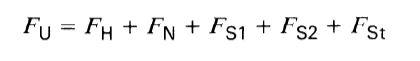
Where,
Main resistance is FH
Secondary resistance is FN
Special main resistance is FS1
Special secondary resistance is FS2
Slope resistance is FSt
Each resistance category is described below along with how these resistances are input or calculated within Belt AnalystTM
The main resistances along the conveyor are comprised of the following:
•Rotational resistance of the carrying and return strands of idlers due to friction in the idler bearings and seals
•Belt advancement resistance due to the pressing down of the idlers into the belt and the recurrent flexing of the belt and bulk material.
The main resistance of any section (flight) or conveyor, carry or return can be described in the following equation:
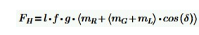
where,
l - is the length of the section or flight of conveyor being calculated
f - is the hypothetical friction coefficient for the subject section of conveyor
g - is the acceleration due to gravity
mR - is the mass per length of conveyor associated with rotating idler parts
mG - is the mass per length of conveyor associated with the conveyor belt
mL - is the mass per length of conveyor associated with the conveyed material
d - is the angle of inclination for the evaluated section of conveyor
The estimate for main resistance is done for each section or flight of the conveyor you are calculating as follows:
•Each flight that has been input into Belt Analyst’s flight tab will have its primary resistance evaluated according to the above equation.
•The length and angle of inclination will automatically be grabbed for each flight from the flights tab.
•The mass of the idlers, belting, and material will be automatically grabbed from the user inputs for each component’s mass on each component’s input tab within Belt AnalystTM. Idler spacing and percent loading for each flight will be taken into account as the user has input on the flights tab.
•The hypothetical friction coefficient is a user input that the user must input into the Belt Analyst program according to his/her own expertise.
•Belt Analyst has the ability to input a different hypothetical friction coefficient for the carry side and return side of the conveyor. These friction factors can be input one of two ways:
•A form will pop up asking for the friction coefficients when you select the ISO calculation method for the first time from the calculation method menu item at the top of the program.
•A form will pop-up asking for the friction coefficients when you click on the white friction coefficients display area on the bottom right side of the program.
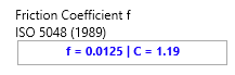
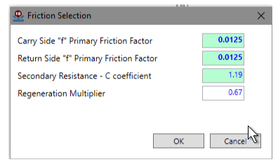
•The input form for the friction coefficients looks like the following image. Please note that the friction coefficient input for the carry side will be used for every flight located on the carry side of the conveyor and the friction coefficient input for the return side will be used for every flight located on the return side of the conveyor.
•There is also an input for “Regeneration Multiplier”. This multiplier is applied to the primary resistances when it is estimated that the forces of gravity on the material will overcome all the resistance on the conveyor and the required power to operate the conveyor becomes negative. Having a multiplier below 1 introduces some conservatism into the calculations of a regenerative conveyor as the highest power demand requirement may be associated with the lowest drag estimate. Again, this multiplier is only applied if the power requirement on the conveyor becomes negative in the active calculation case.
For the selection of the friction coefficients, please refer to the ISO 5048 standard.
Secondary resistances include frictional resistances and inertia resistances that exist only on certain portions of the conveyor. These resistances are calculated from several individual resistances and include frictional losses due to skirting drag on the belt, material drag on skirting within the loading zone, inertial acceleration of material, pulley bearing drag, and belt bending around pulley drag:
Please refer to the ISO 5048 standard for specifics on how to calculate each secondary resistance.
Secondary resistances are calculated within Belt Analyst™ at each location that the resistance exists on the conveyor. For example, if skirting has been added for a loading zone, Belt Analyst™ will add the resistance of the skirting to the loading zone flight.
The C coefficient can be input manually on the same screen as the f coefficient. Alternatively, the C coefficient can be a calculated output based upon the number of secondary resistance items that have been added to the conveyor.
Material Acceleration Resistance:
This resistance is automatically added to the first flight along the carry side of the conveyor that has load AND skirting. This can be seen in the following screen shot; on the flight input with Belt Analyst, a material acceleration load (in this case 2000 mtph worth due to the user input capacity for the conveyor) has been added to the first flight that has a percentage load above zero and also has a skirting length input.
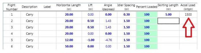
It should be noted that this calculation is directly linked to the user input capacity of the conveyor and the percentage loading input for the flight. The output of this calculation is added to the “Misc Drag” output for the flight. This output is located on the “Output Tension, Drag, Mass, etc…” tab within the flights tab.
Skirtboard Resistance:
This resistance is automatically added to any flight that has a user input skirtboard length on the flights tab. The resistance of the skirtboard pressing against the belt is estimated according to an assumed skirtboard size and contact pressure. This assumed contact pressure is a default that can be changed in the customizable defaults of the Belt Analyst program (listed under “Accessories”). The resistance of the material against the skirtboard is also calculated. The output of the skirtboard resistance calculation is added to the “Misc Drag” output for the flight. This output located on the “Output Tension, Drag, Mass, etc…” tab within the flights tab.
Pulley Bearing and Belt Bending Resistance:
This resistance is automatically added for every pulley added to the conveyor.
The output for the C coefficient can be seen on the bottom right portion of the screen and also within the “Summary Data” tab located on the Drives tab.
Gradient resistance is simply the resistance to conveyor movement associated with gravity and any conveyor lift (or change in height) along a section of conveyor. This gradient resistance can be calculated for any flight with the following equation:
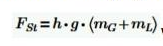
where,
FSt - is the gradient resistance of the flight
h - is the conveyor lift or change in height of the flight
g - is acceleration due to gravity
mG - is the mass of the conveyor belt on the flight
mL - is the mass of the conveyed material on the flight
The gradient resistance is calculated for every flight input into Belt Analyst on the flights tab. Conveyor belt mass and material mass are automatically grabbed from the user inputs for material, capacity, percentage loading for each flight, and belting for the calculation. Please note that the input percentage loading for each flight on the flights tab is taken into account for the calculation of the gradient resistance.
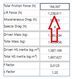
The total gradient resistance for the whole conveyor is output as “Lift Force” within Belt Analyst. This output is located on the “Summary Data” tab located on the Drives tab.
As per ISO, special resistances are resistances that do not occur with all belt conveyors. These special resistances can be summarized in the following categories:
•Special Main Resistances
oDrag resistance due to the forward tilt of the idler in the direction of movement
oResistance due to friction against chute/skirting outside of the loading zone for the full length of the conveyor.
•Special Secondary Resistances
oResistance due to friction with belt and pulley cleaners
oResistance due to friction skirting outside of the loading zone for only part of the length of the conveyor.
oResistances due to discharge plows
Idler Forward Tilt:
If idlers are tilted in the direction of belt travel on the conveyor being analyzed, This can be input within the idler tab when you are calculating within the ISO methodology. The resulting drag is added to the “Special Drag” item that is summarized on the Summary Data tab on the Drives tab.
Cleaner and Plow Resistance:
This resistance is automatically added to any flight that has a user input number for a cleaner or plow on the flights tab. The resistance of cleaners and plows is estimated according to an assumed cleaner/plow contact area and pressure. This assumed contact area and pressure is a default that can be changed in the customizable defaults of the Belt Analyst program (listed under “Accessories”). The resulting drag is added to the “Special Drag” item that is summarized on the Summary Data tab on the Drives tab.
Material Resistance Due to Skirting Outside of Loading Zone:
This resistance is automatically calculated within Belt Analyst™ by adding a length of skirting on any specific flight on the flights tab. Belt Analyst™ will automatically recognize if a loading zone already exists that has accelerated the conveyor load, and treat any skirting outside of that loading zone as simply skirting without the need for material acceleration. Skirting drag against the belt and material will still be calculated. This number will be added to the miscellaneous drag output and the calculation of the C coefficient.
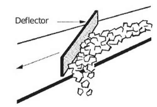
Resistance Due to a Lateral Scraper Discharge:
This resistance is not calculated automatically within Belt Analyst™. To account for a discharge of this type, the user must manually calculate the resistance and then input the drag into the “Extra Drag” column of the flight where the discharge exists on the flights tab. Refer to ISO 5048 on how to calculate this drag.