|
<< Click to Display Table of Contents >> Drive Details |
  
|
|
<< Click to Display Table of Contents >> Drive Details |
|
Drive Details lists the detailed specifications and operating parameters for each drive
Auto or User mode is selected at the top.
![]()
•When the auto mode is selected, the software selects the Nameplate Power.
•In the user mode, the user selects the Nameplate Power.
Additional drive pulleys are added in the Profile page.
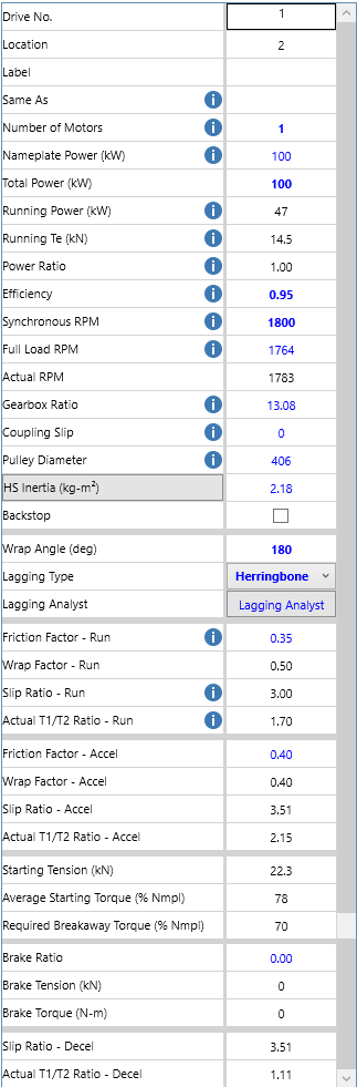
Everything in blue is editable. Everything that is red indicates an out-of-spec condition.
•Variable Speed Mode allows users to vary the Actual Belt Speed from Case to Case to accurately calculate available torque and power when operating the conveyor at speeds between 10 to 120% of nameplate speed of the motor.
•"Same As" automatically updates all drives to the same motor and gearbox properties.
•The Power Ratio is used to select the percentage of the power input by each drive pulley. The total of the power ratio inputs for each drive pulley will add up to 1.0. (When allocating the drive ratio, the program takes the inputted values and then proportionately adjusts the total for all drive/brake locations so the new total is 1.0).
The best way to make an input in this field when multiple drives are used is to put the program in manual calculation mode, input the values making sure the total is 1.0, and then change back to auto calculation mode.
•The drive Efficiency accounts for all mechanical losses in the drive assembly.
•The Synchronous Speed input is used for drive inertia calculations.
•Drive Inertia is estimated in all modes, but a value can be input by the user in the User mode.
This is a possible location for adding the inertia of a flywheel.
Since the estimated inertia is based on motor size, the calculation will often overestimate the inertia if two motors are connected to pulley rather than one larger motor. To improve estimate, the user can enter one motor of half the total power, note the estimated inertia for this size, enter the total connected power (2X), then enter twice the inertia of the smaller motor.
•The Wrap Angle input is used for wrap factor calculations. When changing the wrap angle, the wrap angle of the selected drive pulley will also be changed.
•The Lagging type can be input here, it will also be changed for the selected pulley. When changing the lagging selection, the running and accel/decel friction factors will be reset to the default value specified in Customizable Defaults.
•Friction Factor inputs are editable. Inputting a value of "0" or " " will reset to the default value specified in Customizable Defaults.
•The Average Starting Torque is the calculated torque required to accelerate the conveyor in the inputted start time.
•The Required Breakaway Torque is the torque required to overcome the starting friction which is affected by the breakaway friction multiplier.
The torque available to accelerate the conveyor will be dependent on the motor and drive system selected for the application.
A braking pulley is input into the geometry matrix as a drive. If a single brake is installed that acts only as a brake, the power ratio should be set to zero and the brake ratio to 1.00. Drive pulleys that serve dual duty can have Power Ratios and Brake Ratios that are both greater than 0.00. When allocating the brake ratio, the program takes the inputted values and then proportionately adjusts the total for all drive/brake locations so the new total is 1.0.
•The Brake Ratio is used to select the percentage of the torque input at each pulley. The total of the brake ratio inputs for each pulley will add up to 1.0. (When allocating the brake ratio, the program takes the inputted values and then proportionately adjusts the total for all drive/brake locations so the new total is 1.0).
The best way to make an input in this field when multiple brakes are used is to put the program in manual calculation mode, input the values making sure the total is 1.0, and then change back to auto calculation mode.
This data is similar to that for starting the conveyor except the drive is used for a controlled stop.
•The Deceleration Ratio is the same as the Power Ratio.
•The Average Deceleration Torque is the calculated torque required to stop the conveyor in the inputted time.
See also: Target Tensions