|
<< Click to Display Table of Contents >> Takeup Configuration |
  
|
|
<< Click to Display Table of Contents >> Takeup Configuration |
|
Available in v12 and higher
Available in All
Updated in v20.1
Takeup selection and specification is input using a series of windows in the takeup tab. The configuration of takeup pulleys, carriage, sheaves and rope used in the takeup utilized for the conveyor design is accessed as "Step 2" of defining the takeup.
The fixed takeup type does not have multiple pulleys or carriage; it does not have rope or sheaves affecting belt tension.
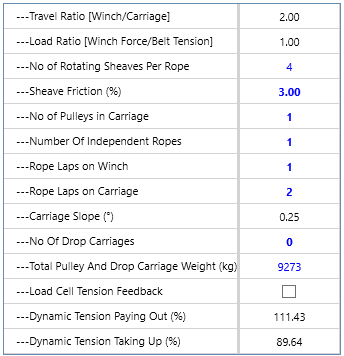
If applicable, input data is entered into a table. If the data value is black or gray, it is calculated by the program or it is an unchangeable default value. Everything in blue is editable; if the blue value is bold, it has been input by the user, otherwise it is a default value. Everything that is red indicates an out-of-spec condition.
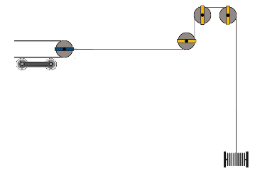
Based in the input data, the program will sketch the defined takeup arrangement. This configuration is approximate, representing mechanical equivalence and shown in 2D. In the arrangement drawing:
• Pulleys are indicated using circle with a blue bar ![]()
•Sheaves are represented as a circle with a yellow bar ![]() ,
,
•Any extra sheaves that are not inline with the rest of the arrangement will be accounted for in the “No of Rotating Sheaves” row count but not shown.
•Belts are thicker bold black lines
•Ropes are thinner non bold lines
•The takeup carriage is indicated with the ![]() symbol.
symbol.
•A weight is shown as ![]()
•An always on winch is ![]()
•An off/on winch is shown as ![]()
•A hydraulic cylinder is ![]()
•If the Number of Pulleys is set to one (typical), there are two laps of belting that must be tensioned so the Weight required is two times the required belt tension. Likewise, two takeup pulleys require a weight or winch line pull, as the case may be, that is four times the required tension.
A series of ropes and sheaves may connect the takeup pulley to the tensioning device -- weight, winch, etc..
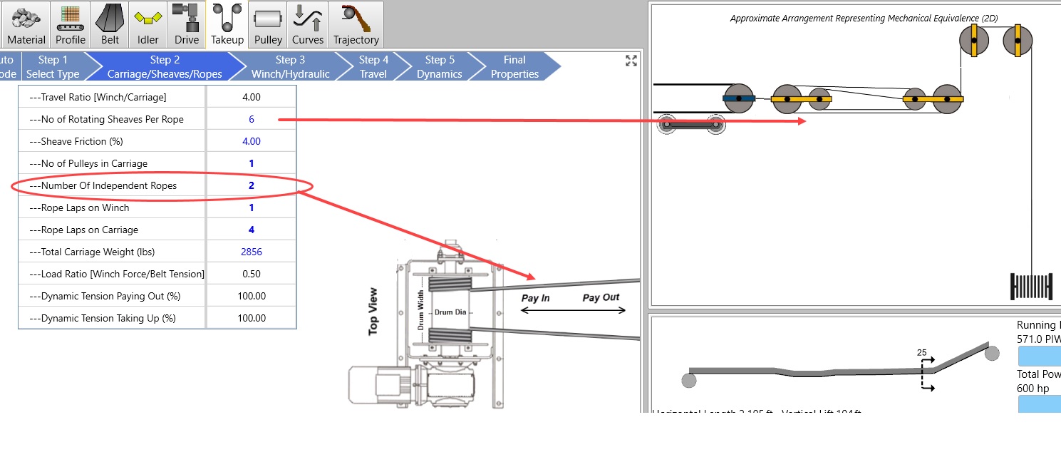
•The program assumes there is one independent rope; if there are more, the user should enter the number of sheaves, rope strands at carriage, and rope strands at weight per independent rope. The number of ropes at each end of the system may affect the load ratio and the ratio of weight travel to carriage travel.
•Sheave Friction may be entered here, otherwise the value shown on the Defaults > Sheave Friction menu item screen will be utilized.
A winch can have 1 or 2 "Independent Ropes" as shown below. The "Number of Rotating Sheaves" are per Rope. The graphic on the right only shows 1 rope regardless of whether the input is 1 or 2.
The takeup system may include a moving carriage. If it is horizontal, it's friction will impact the effective takeup tension.
•Carriage Weight can be entered by the user, or estimated by the program. To estimate the value, enter either a blank or "X" in the input box. The carriage weight should include the weight of any drop carriages installed to support the belt as it travels through the takeup system.
•Carriage friction is assumed to be the same as sheave friction.
•Carriage Slope - the slope of the carriage will automatically determined from the conveyor profile and the flights leading into the takeup pulley. the slope will then be used to calculate gravity "assistance" in carriage motion due to the carriage slope and motion direction. This affects the dynamic paying out and taking up calculation.
•Number of Drop Carriages - For horizontal takeup systems, drop carriages may be placed along the horizontal length of the takeup to support the belt as it travels along the takeup carriage length. The weight of these carriages provides some frictional resistances during takeup movement that is used in the calculation of dynamic paying out and taking up calculation.
Horizontal takeup systems can be arranged such that a load cell is integrated into the takeup rope system. This load cell can measure the effective rope pull acting on the takeup carriage to be used as feedback towards the control of the takeup winch system. Because the load cell can provide direct feedback, the winch can know exactly how hard to pull in order to achieve the specific tension control set points. This effectively allows the winch to overcome any sheave losses in order to provide a more consistent tension set point. In Belt Analyst, selecting the "Load Cell Tension Feedback" option allows the winch to ignore the dynamic paying out and taking up frictional penalties caused by sheave friction during active control.
•The Travel Ratio is the ratio of the weight/winch movement to the carriage movement.
•The Load Ratio is the ratio of takeup weight or pull to the resultant belt tension.
•The Paying Out and Taking up Tension Factors are the amounts (%) that the belt tension is affected by friction during acceleration and deceleration. If belt tension increases for accel/decel then the belt is getting longer; it is "Taking Up" -- friction in the takeup system will decrease the actual takeup tension. If belt tension decreases for accel/decel then the belt is getting shorter; it is "Paying Out" -- friction in the takeup system will increase the actual takeup tension.
While friction will affect the system performance anytime the takeup is moving, only the impact on starting and stopping are considered in this calculation.