|
<< Click to Display Table of Contents >> Import a Full Profile from DXF Drawing |
  
|
|
<< Click to Display Table of Contents >> Import a Full Profile from DXF Drawing |
|
Available in 16 and higher
Available in Suite
Updated in v16.0
User can import a full profile drawing from a DXF file. This includes: Carry Flights, Return Flights, Head and Tail Pulleys, Drives, Bends, Trippers, and a Takeup.
For a review of this new feature, please watch this walk-through video.
The DXF Full Profile Import feature imports a single polyline entity made of lines and arcs which represents your entire belt. Lines are imported as your flights. An arc with a radius greater than 3 meters will be converted into to two flights and given a vertical curve radius matching the radius of the arc. An arc with a radius less than 3 meters will be imported as a pulley with a matching diameter. The head pulley defaults to the furthest pulley to the right and the tail pulley the furthest to the left during the initial import, but can be moved afterwards.
Each pulley should only have one arc, and each vertical curve should only have one arc to be imported correctly into Belt Analyst.
Before starting BA you may need to adjust your DXF drawing to match the format Belt Analyst expects. Refer to the following guidelines while using this feature.
1.BA will only import from layers that have exactly one polyline on them. Other entity types can exist on the layer without effecting the import.
2.The polyline should be a trace of the path of the belt with arcs representing where the belt is going through a vertical curve or wrapping around a pulley.
3.While creating the polyline ensure that the belt is tangent to the arcs that represent pulleys. Otherwise the calculated pulley diameter and center point may be incorrect.
4.The layer can have any name you wish.
5.It is preferred for the polyline to be closed; however, it is not required. The program will close it for you by creating an extra line from the start to the end of the polyline structure, but this may have unintended results especially if the new line is adjacent to a curve.
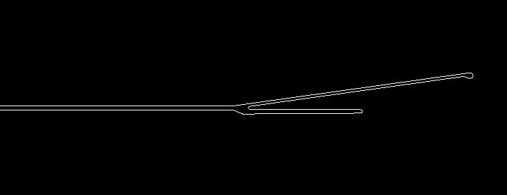
Here is a full DXF drawing from a CAD program
Creating a new file from a DXF Import
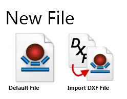
1.Go to the File Menu and select New
2.Select Import From DXF
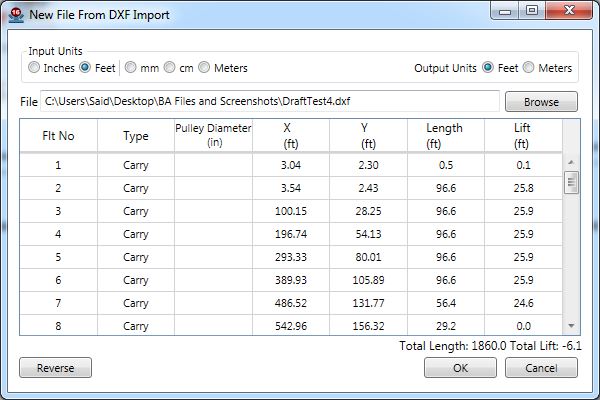
3.In the upper left, select the units the DXF file is drawn in
4.In the upper right, select the units you would like to create the new file with
![]()
5.Click the "Browse" Button, and find the DXF file you wish to import
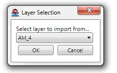
6.If you see a new window, select the layer your profile's polyline is drawn on. Otherwise only one layer with a single polyline was found and BA will import from this layer automatically.
7.The grid should now be populated with the data points from the polyline
8.If needed, you can change which imported pulleys are your head and tail pulley
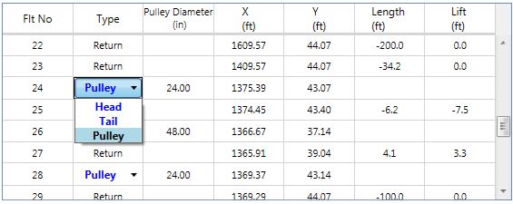
Once the Flight tab is accessible, the user can modify the Takeup location. Also the user can add more drives/pulleys, delete drives/pulleys, or modify drives/pulleys location.
9.If needed, you can reverse the conveyer by clicking the Reverse button
10.Click "Ok" and save your .an2x file with the desired name and path
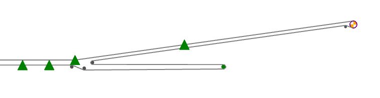
Here is how the drawing will be imported into BA, go to the Flight tab to peak at the 2D drawings.