|
<< Click to Display Table of Contents >> Idler Configuration |
  
|
|
<< Click to Display Table of Contents >> Idler Configuration |
|
The idler input data is input on the main window. If transferred from BA, most the geometry data should agree with the BA design.
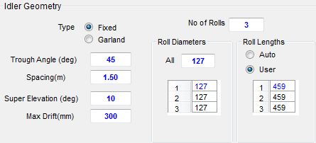
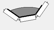
•Trough Angle: The angle between idler rolls.
•Idler Spacing: The spacing between the idlers at the location of the horizontal curve.
•Number of rolls: The number of each idler set.
•Idler Roll Diameter: The roll diameters can all be changed all at once or individual roll diameters can be changed.
•Idler Roll Length: The roll lengths can all be changed at once, or individual roll diameters can be changed.
•Super-elevation Angle: The super-elevation angle of the idler structure at the location of the horizontal curve.
•Maximum Drift: If the drift exceeds the maximum allowable drift distance, the belt is restrained and the restraining force is calculated.
The input roll configuration together with super elevation angle and resultant material position is shown in the idler cross-section figures.