|
<< Click to Display Table of Contents >> Drive Inertia Calculator |
  
|
|
<< Click to Display Table of Contents >> Drive Inertia Calculator |
|
Available in v17 and higher
Available in Pro
Updated in v17.0
The drive inertia calculator allows a user to input inertia values of individual drive components to calculate a more accurate high speed drive inertia to be used within a conveyor calculation. Drive inertia can have a large effect on the starting and stopping of a conveyor.
The drive inertia calculator can be opened by going to the drives tab and clicking on the button located on the "HS Inertia" row label (see image below).
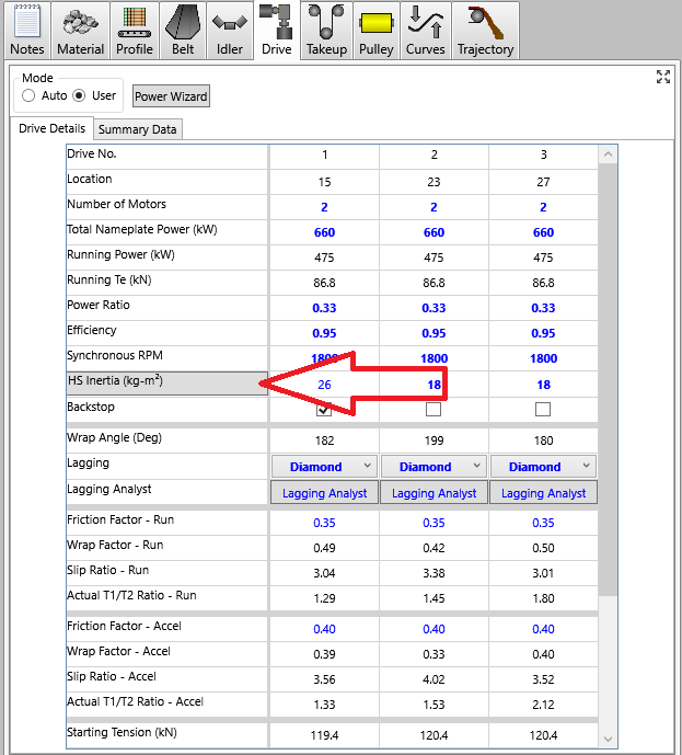
Clicking on the button will open the drive inertia calculator (see screen-shot below):
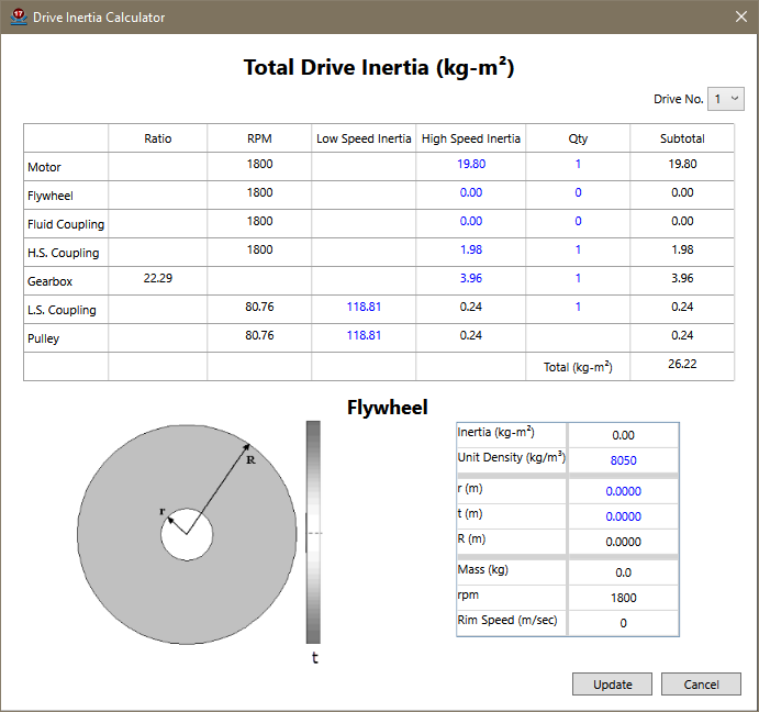
Typical components that make up a conveyor drive system are listed in each row of the calculation grid. Basic information pertaining to the inertia of each component is listed in each column. As is typical throughout all Belt Analyst software, any text shown in black is read only and is a calculated output, while any text shown in blue can be edited by a user. For example, the gearbox ratio is a calculated output value determined from the conveyor speed, motor rpm, and pulley diameter, while motor inertia is initially estimated based upon default data but can be overwritten by a user input value to be used in the calculation.
When using the drive inertia calculator please note the following:
•The displayed/input information within the calculator can be different for each drive on the conveyor. There is a combo box at the top right of the calculator window which allows the user to switch between the different drives on the conveyor.
•The inertia inputs expect units of kg-m^2 when the program is in metric unit mode and lb-ft^2 when the program is in imperial unit mode.
•The input inertia values should be for a single drive component. Use the Quantity column to add the affect of having multiples of the same drive component.
•The default values displayed during initial opening of the calculator are only estimates. Actual drive component inertia values can, in some cases, be quite different.
•The total drive inertia value displayed at the bottom of the main grid is immediately updated after the input of each value.
To model the effect of a flywheel on a drive:
•Input the effective high speed inertia of the subject flywheel and adjust the quantity number to reflect the number of flywheels at the drive.
•The input inertia of the flywheel can also be used to estimate the weight of a simple solid disk flywheel. Use the flywheel grid below the main grid to adjust the dimensions of the flywheel to see the estimated weight and rim surface speed of the flywheel. Note that Belt Analyst will display the surface speed in red if the surface speed is calculated to be more than 150 m/s or 30000 fpm.
Once the user is done inputting their known inertia values and quantities, hitting the update button will take the total inertia value displayed in the calculator and update the HS Inertia value used on the drives tab. The user input values will be remembered the next time the drive inertia calculator is opened unless the user manually changes the drive inertia on the drives tab.
Hitting the cancel button will close the calculator without updating the inertia on the drives tab.