|
<< Click to Display Table of Contents >> Calculation Method |
  
|
|
<< Click to Display Table of Contents >> Calculation Method |
|
Available in v12 and higher
Available in Suite
Updated in v17.2
A new pipe conveyor calculation methodology has been added to Belt Analyst v 17.2. Old pipe conveyor calculation methods are still available for use in the program, however, OCC recommends that the new methodology "Pipe v17+ (OCC)" be used for all pipe conveyor calculations. This methodology update represents a much-needed advance in pipe conveyor friction estimation using well accepted methods normally used for conventional conveyor calculation and adapting them for use with pipe conveyors as well as introducing a brand new methodology for calculating the roll forces at every position along the conveyor due to pipe belt transverse stiffness. This methodology is proprietary to OCC, however, general details about the methodology are discussed here.
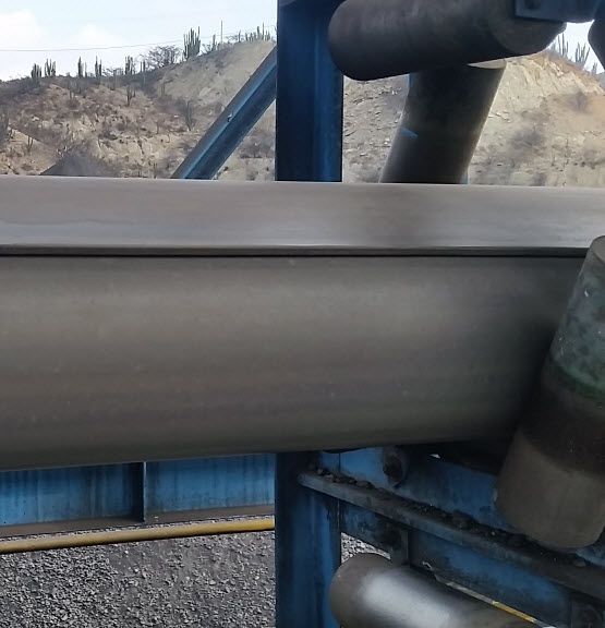
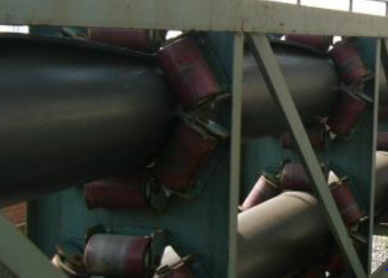
As acknowledged in previous versions of the "Pipe (OCC)" calculation methodology, pipe conveyors differ significantly from conventionally troughed belt conveyors due to the additional roll forces that develop from forcing a belt to form a pipe shape. The roll forces developed from bending the belt into a pipe must be significant enough to prevent the belt from collapsing under its own weight and potential collapsing through vertical and horizontal curves due to local curve stresses. Figure 1 below shows an example of a collapsed pipe conveyor belt with insufficient belt transverse stiffness.
Understanding the magnitude of the roll forces is essential during the design of the pipe conveyor for accurate power, belt, and roller selection. Most modern pipe conveyor designs are developed with cooperation with a qualified belt manufacturer to ensure the compatibility of the belt with the application specifics. No industry standard exists for quantifying required belt transverse stiffness properties for an application.
OCC has adopted quantifying belt transverse stiffness through the product of E x I. The E x I product is commonly used in engineering mechanics for the stiffness of a beam where E is the material's stiffness (Young's Modulus) and I is the section modulus, a property of its dimensions, or simply the thickness for uniform or isotropic plates. Since a belt is composed of different materials of different dimensions, the combined effect is labeled 'EI' to communicate the effect of the composite reaction to bending or stiffness within the belt. Because the EI bending stiffness is not a commonly documented value for belting (nor is there a standard to quantify the bending stiffness of the belt through this number) several options exist within Belt Analyst to estimate the EI bending stiffness:
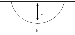
1.Estimating a belt's transverse stiffness based upon a belt ISO703:2007 troughability test results. Troughability is the ratio of F/B of a belt hanging under its own weight. Given a troughability number, an EI bending stiffness number can be estimated. This approach is ok if other options are not available to quantify the belts EI bending stiffness. This is because the most accurate EI measurements for a belt are done when the belt is deformed as close as possible to the condition it will see during use for the application. This is due to the belt's strain dependent and viscoelastic rubber properties. An ISO 703 test does not have a constant belt radius and is therefore will not have the same belt deformation as the application.
1.Direct input of the belt transverse bending stiffness value EI. If tests are performed by bending a belt into the radius of the application, and an EI value is measured, then the EI value can be directly input into the program for use in estimating roll forces.
2.Direct measurement of roll forces from an application specific belt sample in a hex rig at the application specific pipe diameter. If tests are performed by bending a full sized belt sample into the application's pipe diameter, and the pipe roll forces are measured, then the pipe roll forces can be directly input into the program for use in the friction calculation methodology.
The three options listed above are used in Belt Analyst for quantifying belt transverse stiffness. The inputs are located on the Belt tab:
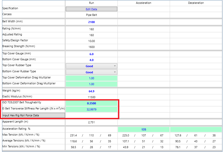
Within the new methodology, belt stiffness must be quantified in order to calculate the forces between each idler roll and the belt. These forces are then used to calculate belt rubber indentation friction and pipe conveyor curve radii limitations.
•If an ISO 703:2007 Belt Troughability number is input, an EI Belt Transverse Stiffness value is calculated based upon the troughability input.
•If an EI Belt Transverse Stiffness value is input, the ISO 703 troughability number is hidden.
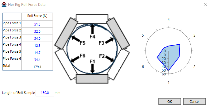
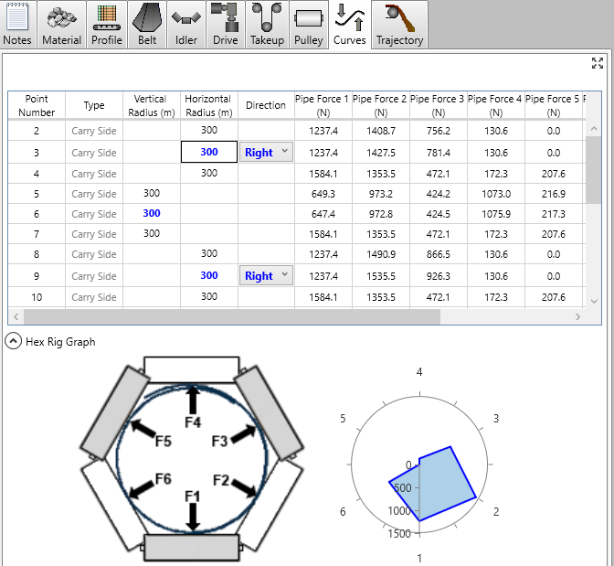
•If a user clicks on the "Input Hex Rig Roll Force Data" button new window will open (see image below) allowing the user to manually input roll forces from a hex rig test stand. In such a case, no EI stiffness values are needed, and the roll forces will all be calculated based upon the hex rig roll force data (roll forces will automatically be adjusted for idler spacing effects).
•It should be noted that it is known that a belt's transverse stiffness is known to change over time (as the belt wears in). Because of this, the ISO703:2007 input, EI input, and Hex Rig Data input are all case variables that can be different from one Belt Analyst calculation case to another. This allows the user to see the effect that changing belt stiffness can have on the design of the conveyor.
Calculating Roll Forces from EI
The EI values calculated from user inputs described above are used to calculate the forces between each idler roll and the belt. These roll forces are extremely important in evaluating pipe conveyor drag, and evaluating whether a belt will collapse under its own weight or through an applications horizontal or vertical curves. OCC developed its own analytical model to calculate roll forces from an EI bending stiffness input. In general, the approach extends the work of Zamiralova and Lodewijks described in the two referenced papers below1,2.
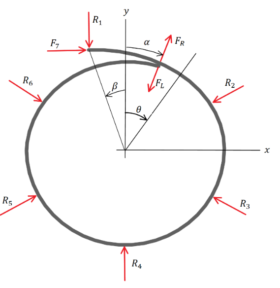
OCC’s analytical model is based on the “ring” of idlers that confines the belt into a pipe shape at a typical idler station. The model presumes that the belt overlaps specified by the angles ![]() and
and ![]() as shown, and that reaction forces R1-R7 confine the belt shape.
as shown, and that reaction forces R1-R7 confine the belt shape.
The results of OCC’s full overlap analytical model have shown good correlation to measured forces.
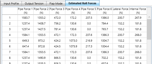
The resulting roll forces are calculated for every flight within Belt Analyst. The output can be seen on the profile tab under the Estimated Roll Forces tab.
Roll Forces within curved sections are output on the curves tab.
Please note that if the resulting roll force for 2 or more of the 6 rolls that make up an idler station drop to 0, then the roll forces for that flight will show red. This signifies that the belt does not have enough transverse stiffness to traverse through that flight without collapsing and losing contact with some of the rolls.
Once the roll forces due to belt stiffness are calculated, they are added to material load forces. Each roll has an effect on rolling resistance and conveyor power. Therefore, the roll forces are a primary input to the frictional loss calculations for a pipe conveyor. OCC’s new methodology developed models to calculate pipe conveyor frictional losses due to:
•Rolling or Main Resistances
oIdler Roll Resistance – Drag due to the idler roll bearings and seals.
oIdler Roll Alignment – Drag due to the average misalignment of idler rolls
oBelt Rubber Indentation – Drag due to the deformation of the belt rubber and viscoelastic properties of the rubber.
oMaterial/Belt Flexure – Drag due to material and belt flexure along the conveyor due to the minor opening and closing of the pipe belt shape between idler sets.
•Point Resistances
oDrag due to cleaners, plows, skirting, and pulleys. Or any point contact with the belt along the conveyor.
oCurve Drag - Drag due to bending the pipe belt shape with material in it into a radius for a curve.
•Lift
oDrag due to lifting material and belt from one height to another.
It should be noted that is important, when calculating a pipe conveyor, that curved sections of the conveyor need to be differentiated from straight sections of the conveyor. This is because curved flights will have significantly different roll forces than straight sections of the conveyor. A new feature has been added to Belt Analyst 17.2 to automatically do this for you called “Finalize Profile”. Finalizing a profile locks a profile from being edited and automatically divides the input flights into curved and non-curved sections.
When using the Pipe v17+ (OCC) methodology, calculations cannot be considered accurate until the conveyor profile is finalized. Because of this, a red “Profile hasn’t been finalized” will show on the main Belt Analyst screen until the profile has been finalized. Furthermore, users cannot view curve details, nor print out their calculations until the conveyor profile has been finalized. See the finalize profile help section for specifics on how to finalize your profile and what the finalize logic does.
Zamiralova, M.E. and Lodewijks, G., A new approach to determine pipe conveyor belt ability to for a stable pipe shape based on its troughability performance, Proceedings, XXI International Conference on Material Handling, Constructions and Logistics, 23-25 Sept., 2015, Vienna, Austria, pp 51-58.
Zamiralova, M.E., F. van Keulen and Lodewijks, G., A new analytical approach to calculate the idler roll load distribution of a pipe conveyor, Proceedings, 11th International Congress on Bulk Material Storage, Handling and Transportation, 2-4 July, 2013, The University of Newcastle, Australia.